We now know that a qubit is the most basic unit of information in quantum computing. Unlike classical bits, which can be either 0 or 1, a qubit can exist in a state of 0, 1, or any superposition of these states. To represent these quantum states, especially when considering the phenomena of entanglement and superposition, we use Dirac Notation, also known as Bra-Ket Notation. This notation, introduced by Paul Dirac, is commonly used in quantum mechanics and quantum computing.
Dirac Notation (Bra-Ket Notation)
Kets (∣⋅⟩):
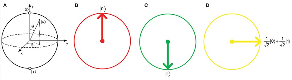
A ket represents a vector in a complex vector space, typically indicating the state of a quantum system. Here are some examples:
- ∣0⟩: Represents the classical state 0
- ∣1⟩: Represents the classical state 1
Bras (⟨⋅∣):
A bra is the conjugate of a ket. While a ket is written as ∣ψ⟩, its corresponding bra is written as ⟨ψ∣.
Bra-Ket Notation helps in expressing and manipulating the states and probabilities in quantum systems, making it a foundational tool in understanding and developing quantum algorithms.
Quantum Gates
Different types of gates that are used for different reasons:
- Hadamard
- Pauli-X
- Pauli-Y
- Pauli-Z
- CNOT
- Toffoli
Hadamard
- often denoted as H
- transforms a qubit into an equal superposition of the ∣0⟩ and ∣1⟩ states
- plays a crucial role in creating quantum superpositions
- widely used in quantum algorithms
In a circuit diagram, the Hadamard gate is represented as : |ψ⟩ — H — |ψ’⟩
Pauli-X
- often referred to as the quantum NOT gate
- a single-qubit quantum gate that flips the state of a qubit
- plays a crucial role in quantum error correction schemes, used to correct bit-flip errors in qubits
In a circuit diagram, the Pauli-X gate is represented as: |ψ⟩ — X — |ψ’⟩
Pauli-Y
- represents a 180-degree rotation around the Y-axis on the qubit Bloch sphere
- manipulates quantum states in a way that combines elements of both the Pauli-X and Pauli-Z gates
- introduces both bit-flip and phase-flip operations
In a circuit diagram, the Pauli-Y gate is represented as: |ψ⟩ — Y — |ψ’⟩
Pauli-Z
- represents a 180-degree rotation around the Z-Axis on the qubit Bloch sphere
- also known as the phase-flip gate
- plays a crucial role in quantum error correction, helping to correct phase errors in qubits
In a circuit diagram, the Pauli-Z gate is presented as: |ψ⟩ — Z — |ψ’⟩
CNOT
- commonly referred to as the CNOT gate
- a fundamental two-qubit gate
- essential for creating entanglement
- flips the state of a target qubit if and only if the control qubit is in the ∣1⟩ state.
- requires two-qubit operation, where the first qubit is the control qubit and the second qubit is the target qubit
Two-qubit operation examples:
- ∣00⟩→∣00⟩
- ∣01⟩→∣01⟩
- ∣10⟩→∣11⟩
- ∣11⟩→∣10⟩
In a circuit diagram, the CNOT gate is represented as:
- Control: |q1⟩ —-●—-
- Target: |q2⟩ —-X—-
Toffoli
- also known as the Controlled-Controlled-NOT gate (CCNOT)
- a universal reversible logic gate
- a three-qubit gate that performs a NOT operation only when both control qubits are in the ∣1⟩ state
- can perform logical operations without loss of information
In a circuit diagram, the Toffoli gate is represented as:
- — •
- — X
- — •

Leave a comment